Facial Bones X-Ray: Waters, Caldwell & SMV
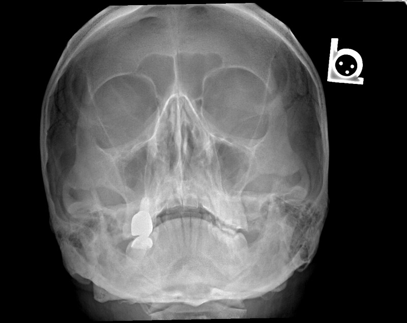
Why Facial Bones Positioning Demands Precision
Facial-bone radiographs remain part of some outpatient and limited-trauma protocols, but they are not the default examination for significant facial trauma. The ACR rates CT maxillofacial without IV contrast as usually appropriate for suspected frontal-bone, midface, or nasal injury after the primary survey; plain radiography has a limited or protocol-dependent role. When radiographs are ordered, accurate positioning matters because the orbital margins, maxillary sinuses, zygomatic arches, and nasal bones overlap.
Positioning terminology also varies among textbooks and departments. This guide states the baseline used for every angle: in the common convention below, standard Waters uses an OML-to-IR angle of about 37°, while modified Waters uses less extension and an OML-to-IR angle of about 55°. Follow the examination order, department protocol, and radiologist preference.
This educational guide reviews six commonly taught projections, not a universal six-image series. It does not replace a local protocol card or clinical judgment.
📖 What You'll Learn
By the end of this guide, you'll know common centering points, baseline relationships, and evaluation criteria for Waters (parietoacanthial), modified Waters, Caldwell (PA axial), lateral facial bones, SMV (submentovertex), and lateral nasal bones—plus when trauma precautions or CT should take priority.
Anatomy of the Facial Skeleton: What You're Imaging
The facial skeleton consists of 14 bones, including the mandible. The mandible is often examined under a separate imaging protocol:
| Bone | Count | Key Landmark |
|---|---|---|
| Maxilla | 2 | Inferior orbital rim, maxillary sinuses, alveolar ridge |
| Zygomatic | 2 | Cheek prominence, zygomatic arch, lateral orbital wall |
| Nasal | 2 | Superior bridge of the external nose |
| Lacrimal | 2 | Medial orbital wall (smallest facial bones) |
| Palatine | 2 | Posterior hard palate |
| Inferior Nasal Conchae | 2 | Lateral nasal wall |
| Mandible | 1 | Jaw (often imaged separately) |
| Vomer | 1 | Nasal septum |
Depending on the indication, images may be assessed for fracture or displacement, sinus opacification/fluid, and radiopaque foreign material. Radiographs do not exclude a fracture or radiolucent foreign body. Three classic midface fracture patterns are:
- Le Fort I — Transverse maxillary fracture above the tooth apices
- Le Fort II — Pyramidal pattern through the maxilla, nasal region, and inferior orbital rims
- Le Fort III — Craniofacial disjunction involving the nasofrontal/frontozygomatic regions and zygomatic arches
🩻 Clinical Context — Le Fort Classification
Classic Le Fort patterns require pterygoid-plate fractures, and real injuries may be asymmetric or combine levels. Do not reduce the system to “teeth, nose, entire face” or assume that a higher number alone predicts clinical severity. CT maxillofacial without IV contrast is used to define suspected midface fractures; a Waters radiograph is not sufficient to exclude or map a Le Fort injury.
Key Landmarks and Baselines
Mastering facial bone positioning comes down to the same three anatomical lines used in skull radiography, plus a few specific facial landmarks:
| Baseline / Landmark | Definition | Used For |
|---|---|---|
| Orbitomeatal Line (OML) | Outer canthus → center of EAM | Waters variants, Caldwell, PA/AP skull |
| Infraorbitomeatal Line (IOML) | Infraorbital margin → upper margin of EAM | SMV, Towne variant |
| Acanthion | Midline point at the base of the anterior nasal spine | Waters CR exit point |
| Nasion | Depression at bridge of nose | Caldwell CR exit point |
| Mental Point (Mentum) | Tip of chin | Lateral positioning reference |
| Glabella | Smooth prominence between eyebrows | PA/AP skull landmark |
| Gonion | Angle of the mandible | Mandible oblique positioning |
🚨 Positioning Pearl — Contact Point vs CR Exit
For the common erect PA Waters setup, the chin contacts the IR and the neck is extended until the MML is approximately perpendicular to the IR (OML about 37° to it). The acanthion is the CR exit landmark; it is not the receptor contact point. Do not force extension in an uncleared trauma patient.
Projection 1: Waters — Parietoacanthial
The Waters view (parietoacanthial projection) demonstrates the maxillae and maxillary sinuses, inferior orbital rims, zygomatic bones, and nasal cavity. Its inclusion is indication- and department-dependent.
Patient Position
- Erect or prone according to the indication and equipment; erect positioning is useful when sinus fluid levels are relevant
- Extend the neck, if safe, to bring the OML to approximately 37° to the IR
- The chin rests against the IR; adjust until the MML is approximately perpendicular to the IR
- Midsagittal plane perpendicular to the IR
- Do not extend the neck until cervical-spine injury has been excluded when trauma is suspected
Baseline
- Common protocol: OML approximately 37° from the plane of the IR (equivalent to MML approximately perpendicular)
Central Ray
- Perpendicular (0°) to the IR
- Directed along the midsagittal plane to exit at the acanthion
Technical Factors
- IR/SID: commonly 24 × 30 cm (10 × 12 in), portrait, at about 100 cm (40 in); follow local equipment protocol
- Grid: protocol-dependent; use the department technique chart and tight collimation
- Breathing: Suspend respiration
Evaluation Criteria
- Petrous ridges projected just inferior to the maxillary sinuses with the maxillary sinuses shown without petrous superimposition
- Inferior orbital rims and zygomatic bones demonstrated
- Nasal septum centered (no rotation)
- Both zygomatic bones symmetric
Projection 2: Modified Waters — Orbital-Floor Protocol Variant
The modified Waters is a commonly taught radiographic variant for the orbital floor and inferior orbital rim. It uses less neck extension than standard Waters. It should not be presented as a substitute for CT when a clinically significant orbital or midface fracture is suspected.
Patient Position
- Erect or prone with the chin against the IR, midsagittal plane perpendicular
- Use less neck extension than standard Waters: in a common convention, bring the OML to approximately 55° from the IR
Central Ray
- Perpendicular (0°) to the IR
- Exits at the acanthion (same as standard Waters)
Key Difference
Compared with standard Waters, the larger OML-to-IR angle (approximately 55° vs 37°) reflects less extension. It projects the petrous ridges into the lower half of the maxillary sinuses, allowing the orbital floors to be visualized through the sinuses. Angle descriptions are not interchangeable unless the same baseline and reference surface are stated.
Evaluation Criteria
- Orbital floor and infraorbital rim clearly demonstrated
- Petrous ridges projected in the lower half of the maxillary sinuses
- No rotation — symmetric orbital margins
| Feature | Standard Waters (common variant) | Modified Waters (common variant) |
|---|---|---|
| OML to IR | About 37° | About 55° |
| Neck extension | More | Less |
| Radiographic emphasis | Maxillae/maxillary sinuses and facial bones | Orbital floors/inferior rims |
| Petrous ridges | Just below maxillary sinuses | Lower half of maxillary sinuses |
📝 Study Note — State the Baseline
For the convention used here: standard Waters = OML about 37° to the IR; modified Waters = OML about 55° to the IR. The modified view uses less extension and places the petrous ridges in the lower half of the maxillary sinuses. Some resources use different line/beam descriptions, so never quote a bare angle without its reference.
Projection 3: Caldwell — PA Axial
The Caldwell view (PA axial) is used in facial bone imaging to evaluate the superior orbital fissures, frontal sinuses, ethmoid sinuses, and orbital margins. It's the same projection used in the skull series, but the interpretive focus shifts to the facial structures.
Patient Position
- Prone or erect with forehead and nose against the IR/bucky, as equipment and patient condition permit
- Flex/extend as needed to place the OML perpendicular; unlike Waters, the forehead and nose contact the IR
- Midsagittal plane perpendicular to the IR
Baseline
- OML perpendicular to the IR
Central Ray (Common Facial-Bone Variant)
- Angled 15° caudad to the OML
- Exits at the nasion
Evaluation Criteria
- Petrous ridges projected into the lower third of the orbits
- Superior orbital fissures clearly visible
- Frontal and ethmoid sinuses well demonstrated
- No rotation (symmetric orbital margins)
For this 15° caudad variant, ridges higher than the lower third suggest insufficient caudad angulation or head-position error; ridges below the orbits suggest excessive caudad angulation or head-position error. Assess baseline alignment as well as tube angle before deciding on a correction.
Projection 4: Lateral Facial Bones
The lateral facial-bones projection provides an overall profile with bilateral structures largely superimposed. It can show gross displacement, but superimposition limits fracture assessment and CT is preferred for significant facial trauma.
Patient Position
- Erect or recumbent — same setup as the lateral skull
- Head in true lateral — midsagittal plane parallel to the IR
- Interpupillary line perpendicular to the IR
- Adjust the IOML perpendicular to the front edge of the IR; place the side of interest closest when one side is specified
Central Ray
- Perpendicular to the IR
- Centered to the zygoma, approximately midway between the outer canthus and EAM (follow the local protocol)
Technical Factors
- IR size: 24 × 30 cm (10 × 12 in), portrait
- SID: 100 cm (40 in)
- Grid: Yes
Evaluation Criteria
- Facial bones in profile with bilateral orbital roofs and mandibular rami superimposed
- Orbital roofs superimposed (no tilt)
- Mandibular rami superimposed (no rotation)
- Entire facial skeleton included with the zygoma near image center
Projection 5: SMV — Submentovertex
The facial-bone SMV can demonstrate both zygomatic arches with reduced superimposition. A skull-base SMV uses different centering and should be labeled as a separate protocol variant. For suspected zygomaticomaxillary-complex injury, CT defines the full fracture pattern better than radiographs.
Patient Position
- Supine or erect only when the patient can safely extend the neck
- Hyperextend the neck until the IOML is parallel to the IR
- The vertex rests against the IR/bucky
- Keep the midsagittal plane perpendicular to the IR; support as needed without forcing the neck
Central Ray (Bilateral Zygomatic-Arch Variant)
- Perpendicular to the IOML and IR
- Centered on the midsagittal plane to pass through the arches, commonly approximately 2.5 cm (1 inch) posterior to the outer canthi
- A skull-base SMV instead centers through the sella region; do not mix its centering landmarks with the bilateral-arch protocol
Evaluation Criteria
- Zygomatic arches clearly demonstrated (no superimposition)
- Arches symmetric and lateral to the cranial cortex, without rotation
- Mandibular condyles anterior to the petrous portions
Safety Consideration
The SMV requires marked neck extension. Do not remove immobilization or extend the neck if cervical-spine injury is suspected or not yet excluded. Obtain clearance from the trauma team and follow the ordered/local alternative; CT is commonly used when significant facial injury is suspected. Limited motion from pain or arthritis may also make the projection unsafe or nondiagnostic.
Trauma Safety — SMV
Never trade spinal precautions for a requested projection. Keep immobilization in place and escalate an unsafe position to the radiologist/trauma team rather than improvising a substitute.
Projection 6: Nasal Bone — Lateral View
The nasal bones are commonly injured. Whether radiographs are obtained varies with the clinical question; the ACR rates CT maxillofacial without contrast as usually appropriate for suspected nasal injury after the primary survey, while radiography may be appropriate in selected cases. A lateral nasal-bone view requires careful centering and a small-part technique.
Patient Position
- True lateral with the interpupillary line perpendicular to the IR
- A common protocol obtains both right and left laterals for comparison; name the projection by the side against the IR. Follow local protocol if only one side is ordered
Central Ray
- Perpendicular to the IR
- Centered to the nasal bones, commonly about 1.3 cm (1/2 inch) inferior to the nasion; some protocols center at the nasion
Technical Factors
- IR/SID: commonly 18 × 24 cm or 8 × 10 in at about 100 cm (40 in)
- Technique: commonly nongrid, small focal spot, low kVp/low mAs, and tight collimation; use the department technique chart because detector and grid practices vary
- Breathing: Suspend respiration
Evaluation Criteria
- Nasal bones in profile — bridge, tip, and base of nose visible
- No tilt or rotation; orbital roofs and mandibular rami should be superimposed
- Soft tissue outline of the nose visible
Common Projection Variants Summary
| Projection | Beam / Baseline | Centering Landmark | Radiographic Emphasis |
|---|---|---|---|
| Waters (Parietoacanthial) | Perpendicular CR; OML about 37° to IR | Exit acanthion | Maxillae/maxillary sinuses, inferior orbital rims, zygomatic bones |
| Modified Waters | Perpendicular CR; OML about 55° to IR (less extension) | Exit acanthion | Orbital floors through lower maxillary sinuses |
| Caldwell (PA Axial) | Common facial-bone variant: 15° caudad to OML | Exit nasion | Orbital margins, frontal/ethmoid region |
| Lateral Facial Bones | Perpendicular | Zygoma, midway outer canthus–EAM | Overall facial profile and gross displacement |
| SMV (bilateral arches) | Perpendicular to IOML/IR | MSP, about 2.5 cm posterior to outer canthi | Bilateral zygomatic arches |
| Nasal Bone Lateral | Perpendicular | Nasal bones, often 1.3 cm inferior to nasion | Nasal bones and overlying soft tissue in profile |
Note: There is no universal “complete facial-bone series.” Projection selection varies by indication, equipment, and department. For significant acute facial trauma, do not delay appropriate CT or compromise cervical-spine precautions to complete radiographic views. Check the order and protocol card before starting.
Positioning Errors: Quick Reference
| Error | Likely Cause | Correction |
|---|---|---|
| Petrous ridges overlap maxillary sinuses (standard Waters) | Insufficient neck extension / OML-to-IR angle too large | If safe, extend toward the protocol target (about 37° OML-to-IR) |
| Petrous ridges projected far below maxillary sinuses (standard Waters) | Excessive extension / OML-to-IR angle too small | Reduce extension while keeping the chin as the contact point |
| Orbital floor not adequately shown on an ordered modified Waters | Standard rather than modified position, rotation, or exposure issue | Confirm the ordered variant and local baseline; do not repeat solely to “find” a suspected fracture—escalate when CT is indicated |
| Asymmetric maxillary sinuses (Waters) | Rotation | Check midsagittal plane centered and perpendicular |
| Petrous ridges above lower third of orbit (15° Caldwell variant) | Insufficient caudad angulation or OML not perpendicular | Recheck baseline and then tube angle |
| Orbital roofs not superimposed (Lateral) | Tilt | Check interpupillary line perpendicular to IR |
| Mandibular rami doubled (Lateral) | Rotation | Check midsagittal plane parallel to IR |
| Zygomatic arches obscured (SMV) | Insufficient safe extension, rotation, or incorrect centering | Recheck IOML/IR alignment and centering only if the neck is cleared; otherwise escalate |
| Nasal bone blurred | Motion or exposure time too long | Immobilize gently, suspend respiration, and use the validated small-part technique |
| Nasal-bone detail inadequate | Technique, processing, scatter, collimation, or motion | Review the exposure indicator and technique chart; do not infer the cause from displayed brightness alone |
Study Review: Facial Bones
ARRT content specifications identify head positioning knowledge but do not promise a fixed number or frequency of facial-bone questions. Focus on relationships and safety rather than unsupported question-count predictions:
- Standard Waters: perpendicular CR exiting the acanthion; common setup has the OML about 37° to the IR and the chin against the IR
- Modified Waters: less extension, with the OML about 55° to the IR in this convention; petrous ridges in the lower half of the maxillary sinuses
- Caldwell facial-bone variant: commonly 15° caudad exiting the nasion; petrous ridges in the lower third of the orbits
- Lateral facial bones: center to the zygoma midway between outer canthus and EAM, not to the lateral-skull centering point
- SMV bilateral arches: IOML approximately parallel to the IR; never extend an uncleared cervical spine
- Le Fort patterns: all classic levels include pterygoid-plate fracture; CT defines the pattern
- Zygomaticomaxillary-complex and orbital-floor trauma: radiographic views may demonstrate components, but CT is preferred for significant suspected injury
- The acanthion is the midline point at the base of the anterior nasal spine; it is a Waters exit landmark, not the IR contact point
- The OML is the primary baseline for most facial bone projections (not the IOML)
📝 Study Note — Do Not Mix Geometries
Tube angle and head-baseline angle are different variables. A 15° caudad Caldwell describes the CR relative to the OML; 37° and 55° Waters values here describe the OML relative to the IR with a perpendicular CR. Evaluate each projection against its stated protocol rather than applying a universal “steeper means lower” shortcut.
Clinical Pearls: Tips from the Techs
- Trauma safety first — Confirm stability and cervical-spine clearance before Waters or SMV extension. Maintain immobilization until the responsible clinical team clears movement.
- Do not invent a shortened series — If pain or condition prevents an ordered view, discuss it with the radiologist/ordering team. Significant facial trauma generally warrants CT rather than a self-selected “best” radiograph.
- Explain the position — For Waters variants, tell the patient how the face and chin will contact the upright unit and allow comfortable mouth breathing. Clear instructions reduce motion.
- Collimate to the ordered anatomy — Receptor size does not replace collimation. Include the required anatomy while limiting irradiated volume and scatter.
- Remove removable artifacts — Glasses, jewelry, hair accessories, and removable dental appliances can obscure anatomy. Do not remove fixed or medically necessary devices.
- Align, don't force — Use visible/palpable landmarks gently and reassess the baseline. Never force a painful or restricted neck to match a nominal angle.
- Use a validated technique chart — Select kVp, mAs, focal spot, grid, SID, and detector settings for the equipment and patient. For nasal bones, a nongrid low-kVp/low-mAs small-part technique is common, but “half the facial-series mAs” is not a universal rule.
☢ Exposure and Patient Shielding
Use justification, correct positioning, tight collimation, the department technique chart, and repeat analysis to optimize dose. Routine contact gonadal or fetal shielding is no longer recommended by major medical-physics guidance because it offers negligible benefit and can obscure anatomy or interfere with exposure control; follow current law and facility policy, and never place shielding in the primary beam. Ask about pregnancy according to local policy without delaying urgent indicated care.
Sources and Scope Notes
- ACR Appropriateness Criteria®: Imaging of Facial Trauma Following Primary Survey — modality recommendations for suspected frontal, midface, nasal, and mandibular injury.
- Mickelsen W, Hobbs D, Wertz C. Lateral Positioning of the Nasal Bones Using Digital Radiography — peer-reviewed discussion of bilateral lateral nasal images, nongrid technique, small focal spot, and low-kVp/low-mAs practice.
- ARRT Examination Content Specifications — scope reference; it does not support a guaranteed facial-bone question count.
- AAPM Position Statement PP 32-A (archived): Use of Patient Gonadal and Fetal Shielding — rationale for discontinuing routine shielding; apply current facility and jurisdictional policy.
Scope: Numeric positioning values above are explicitly labeled as common positioning-text conventions because protocols vary. They should be reconciled with the current protocol card and radiologist preference. This page does not claim verification against a specific edition or page of Clark's or Merrill's.