The X-Ray Tube: Cathode, Anode, and the Line-Focus Principle
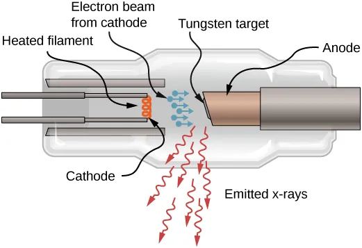
Every radiograph you'll ever produce depends on one piece of hardware: the X-ray tube. It's the engine of the X-ray imaging system — and it's one of the highest-yield topics on the ARRT registry. This guide walks through every component you need to know, from the filament that boils off electrons to the rotating anode that survives the heat, plus the line-focus principle and heel effect that exam questions love.
Key Concept
The X-ray tube converts electrical energy into X-radiation in two steps: the cathode produces electrons (thermionic emission), and the anode converts their kinetic energy into X-ray photons — with more than 99% of that energy becoming heat.
The Cathode: Where Electrons Are Born
The cathode is the negative side of the X-ray tube. It has two primary parts: the filament and the focusing cup.
The Filament
The filament is a small coil of wire — roughly 2 mm in diameter and 1-2 cm long — similar to the heating element in an oven roaster but much smaller. When the filament current is high enough (about 4 A or more), the outer-shell electrons are literally boiled off the filament. This process is called thermionic emission.
- Filament material: usually thoriated tungsten — tungsten with 1-2% thorium added
- Why tungsten? Its very high melting point (about 3,422°C for pure tungsten) means it doesn't vaporize easily at operating temperature
- Why add thorium? The small thorium addition increases the efficiency of thermionic emission and prolongs tube life
ARRT Tip
The filament circuit controls mA (x-ray quantity). More filament current = more electrons boiled off = more X-rays. That's why mA is described as the quantity control — it determines how many photons, not how energetic they are.
The Focusing Cup
The filament is embedded in a metal cup called the focusing cup. The cup is negatively charged, so it electrostatically condenses the electron beam onto a small area of the anode. Without it, electrons would spread out and strike the anode over a large, poorly controlled area.
Dual-Focus (Dual-Filament) Cathodes
Most X-ray tubes have two filaments and two focal spots:
| Focal spot | Typical size | When it's used |
|---|---|---|
| Small | About 0.1-0.5 mm | When better spatial resolution is required (e.g., fine bone detail) |
| Large | About 0.4-1.2 mm | When high-heat techniques are needed (e.g., heavy body parts, high mA) |
At roughly 400 mA and above, only the large focal spot is recommended — the small focal spot concentrates so much heat that the anode's heat capacity could be exceeded.
The Anode: Where X-Rays Are Made
The anode is the positive side of the tube and the target that electrons strike. It's usually a disc of tungsten-rhenium (for the focal track) bonded to a molybdenum or graphite body, which conducts heat away efficiently.
Stationary vs. Rotating Anodes
- Stationary anode: found in dental, portable, and some specialty units where heat loading is low
- Rotating anode: standard for general radiography — the disc spins so each exposure spreads heat across a large circular focal track instead of one small point
The Induction Motor
The anode rotates with no mechanical connection through the glass envelope. It uses an induction motor:
- The stator — fixed electromagnets mounted outside the glass envelope
- The rotor — a copper-and-iron cylinder inside the envelope, attached to the anode disc
- Stator coils energize in sequence, creating a rotating magnetic field that drags the rotor and anode around with it
Standard rotating anodes run at about 3,000-3,600 rpm; high-speed anodes reach 9,000-10,000 rpm. After a high-speed exposure you'll hear the rotor slow and stop — the motor is briefly put into reverse to brake the disc (coast time in newer tubes is about 60 seconds if left alone).
ARRT Tip
The rotor is inside the vacuum; the stator is outside. This "motor without a shaft seal" question appears frequently on the registry — remember: stator outside, rotor inside.
Focal Spot Size and Spatial Resolution
The effective focal spot size is the focal spot as projected onto the patient and image receptor — and it's the value used to identify a tube as "large" or "small" focal spot. In general, a smaller focal spot gives better spatial resolution, but it also concentrates heat in a smaller area, which limits how much exposure you can safely use.
The Line-Focus Principle
The line-focus principle solves the classic tube design problem: you want a large target area for heat capacity but a small effective focal spot for sharp images.
The solution is to angle the target face. By angling the anode, the actual area of electron interaction is much larger than the effective (projected) focal spot. The relationship is:
Formula
Effective focal spot = actual focal spot × sin(target angle)
Smaller target angle → smaller effective focal spot → better resolution (but a stronger heel effect and smaller field coverage). Diagnostic X-ray tubes use target angles of roughly 5° to 15°.
Some modern tubes use biangle targets — two different target angles on the same anode — so each focal spot is optimized separately.
The Heel Effect
The heel effect is the uneven beam intensity across the X-ray field: X-ray intensity is higher on the cathode side and lower on the anode side. Photons produced deeper in the target must travel through more target material before exiting, so they're preferentially absorbed on the anode side.
The heel effect is more pronounced when:
- The SID is short (intensity difference is larger over a smaller field)
- The image receptor is large
- The target angle is steep (small)
Clinical pearl: position the anode toward the thicker body part (e.g., the hip or the thicker end of the femur) and the cathode toward the thinner part — the thicker anatomy needs more photons, which is exactly where the cathode side delivers them.
Envelope, Housing, and Support
The tube insert sits inside a lead-lined housing that limits leakage radiation and contains insulating oil, which both cools the tube and provides electrical insulation. The evacuated glass or metal envelope lets electrons travel from cathode to anode without colliding with gas molecules.
Because a diagnostic tube is heavy, it needs a sturdy support system. The six main mounting methods are:
- Ceiling support — the most common; telescoping column on ceiling rails over the table
- Floor-to-ceiling support — a column riding on both a ceiling rail and a floor rail
- Floor-mounted system
- Fluoroscopy (over-table/under-table tube)
- C-arm — used in surgery and fluoroscopy
- Portable / mobile machines
Three Main Causes of X-Ray Tube Failure
| Cause | What happens |
|---|---|
| 1. Filament vaporization (most common) | Over many exposures the filament slowly boils away; eventually it breaks open, and the tube can no longer produce electrons |
| 2. Anode cracking / pitting | Excessive heat causes the target surface to crack or pit, which ruins image quality and can end the tube's life |
| 3. Anode bearing wear | The rotating anode's bearings wear out, making the rotor noisy, rough, or eventually locked; this follows many high-speed rotations |
A fourth failure mode — cracking of the glass envelope — destroys the vacuum and instantly kills the tube. This is why you never use the tube rating charts to push a tube beyond its limits.
Tube Rating Charts: Protecting the Tube
A tube rating chart tells you the maximum allowable mA for a given exposure time at a given kVp (each kVp gets its own curve). It exists because the anode can only absorb so much heat per exposure without being damaged.
How technologists use it:
- Find the exposure time on the horizontal axis
- Follow the curve for the kVp you plan to use
- Never exceed the mA that the curve allows for that time
Modern systems with automatic exposure control (AEC) help protect the tube, but understanding rating charts is still core registry material — and essential when you work with older equipment.
Key Takeaways for the Registry
- Cathode = negative (filament + focusing cup); anode = positive (target)
- Thermionic emission — heat releases electrons from the filament; filament current controls mA (quantity)
- kVp controls energy — higher kVp accelerates electrons faster and produces more penetrating X-rays
- Line-focus principle — angled target gives a large actual area (heat) and small effective focal spot (resolution); effective = actual × sin θ
- Heel effect — anode side is dimmer; anode toward the thicker body part
- Rotating anode — induction motor: stator outside, rotor inside; 3,000-10,000 rpm
- Filament vaporization is the #1 tube failure; rating charts prevent overload
For the complete production story — how those electrons become bremsstrahlung and characteristic radiation — read X-Ray Production: How X-Rays Are Made. And to see how tube output shapes your image, review kVp & mAs Explained: 15% Rule, Density, Contrast.
Frequently Asked Questions
What are the main components of an X-ray tube?
The two main electrodes are the cathode (negative: filament + focusing cup) and the anode (positive: the target), inside an evacuated envelope in a lead-lined housing. The anode is usually a rotating tungsten-rhenium disc spun by an induction motor.
What is the line-focus principle?
Angling the anode target so the actual electron impact area is large (good heat capacity) while the effective focal spot is small (good resolution). Effective focal spot = actual × sin(target angle); diagnostic target angles are about 5°-15°.
What causes the heel effect?
Photons from deeper in the target are absorbed by target material, so intensity is lower on the anode side. It's worse with short SID, large image receptor, and steep target angle. Positioning the anode toward the thicker body part reduces its visible effect.
Why is the anode rotated?
More than 99% of electron energy becomes heat. Rotating spreads heat over a large focal track, allowing much higher tube loading without melting the target.
What causes X-ray tube failure?
Most commonly filament vaporization (the filament breaks). Also anode cracking/pitting, bearing wear, and glass envelope cracking (which destroys the vacuum). Rating charts prevent the overheating that accelerates these failures.
Authoritative Sources
- IAEA, Diagnostic Radiology Physics: A Handbook for Teachers and Students, Chapter 5 (X-ray tubes: cathode, anode, focal spot, heel effect, ratings).
- OpenStax University Physics, "Atomic Spectra and X-rays" (X-ray tube diagram and production physics).
- Standard radiologic technology texts used in accredited programs (Bushong; Carlton & Adler) — tube construction, line-focus principle, and rating charts.
- U.S. FDA, Medical X-ray Imaging (equipment safety and quality-control context).
📚 Related Articles
Test Your Knowledge
Try these ARRT-style multiple choice questions based on this article. Click an option to check your answer — correct answers turn green, wrong ones turn red.
Filament current controls thermionic emission — more filament current boils off more electrons, increasing mA and x-ray quantity. The focusing cup only shapes the electron beam; it does not control quantity.
Effective focal spot = actual focal spot × sin θ. A smaller target angle produces a smaller effective focal spot and better spatial resolution.
X-ray intensity is lower on the anode side because photons produced deeper in the target are absorbed by target material on their way out. Position the anode toward the thicker body part to minimize its effect.
Over thousands of exposures the filament slowly boils away (vaporizes) until it breaks open, ending the tube's life. Anode pitting and bearing wear are also causes, but filament vaporization is the most common.